Daniel Morgan
I write code that works (usually).
Learning assembly with an AVR MCU
In an effort to get a better understanding of how the code I write on a daily basis really works I decided to learn some assembly programming.
High level languages are too productive, time to be a hipster: "Beginner's introduction to AVR assembler language" https://t.co/hZZEwpg54O pic.twitter.com/5iuZILvn5X
— Daniel Morgan (@Morgan345) July 11, 2017
What is Assembly?
The first realisation I had after deciding to try and learn this "Assembly" thing was that it isn't a single programming language. It's more like a class of language, designed to make writing instructions for a specific CPU manageable. It's one step removed from flipping the bits yourself.
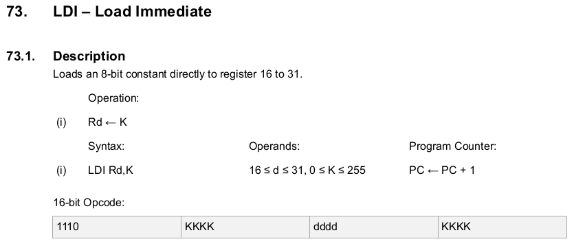
The machine code the CPU will execute looks like 1110 1111 0000 1111, but with an assembler we can write LDI r16 255 instead. It's not exactly a descriptive function name, but it's an improvement.
And I have absolutely no idea why the K constant is split up like that in the opcode, with the register destination sandwiched in between. If anyone has any insight into that I'd love to hear it.
Knowing the hardware
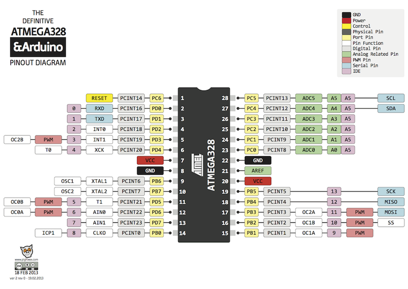
Next I discovered that I needed to know the capabilities of the hardware I wanted to program. I chose an AVR ATmega328P, which is the microcontroller (MCU) used on the Arduino Uno, and ordered one from Amazon with a few components to make wiring it up on a breadboard easier.
I downloaded the data sheet and instruction set PDFs and got to studying the architecture of the MCU. With that I learned what registers I had to store data in, how to read from and set the output of the pins, and how the timers work.
Programming the MCU
Problem: How do I write assembly code on my modern 64-bit computer with 16GB RAM, then run it on this 8-bit MCU with just 32KB of program memory?
Quick solution: Use what was to hand - I popped the MCU into the DIP socket of an Arduino Uno and connected that to my computer via the Arduino's USB cable. I could program it but then I had to pop it out again and place it back in a breadboard to test anything.
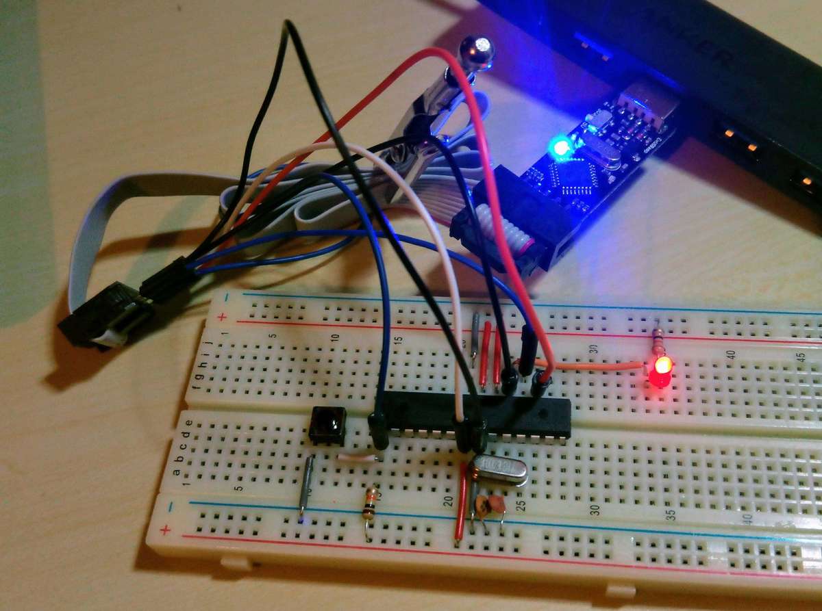
Proper solution: The next day I ordered a USB ISP programmer and wired it up directly.
Previously I was using the Arduino IDE to get the code onto the MCU. After wiring in the serial interface and cutting the Arduino out of the setup altogether I had to find something else. AVRDUDE is a command line utility for writing machine code to the MCU's 32KB of available ISP flash memory.
Let's put it all together.
Step 1: Write the assembly code to hello_world.asm
.DEVICE ATmega328P
    LDI r16, 0b00100000
    OUT 0x04, r16
    OUT 0x05, r16
Start:
    RJMP Start
Step 2: Assemble to machine code hello_world.hex
avra hello_world.asmStep 3: Load machine code onto the MCU
avrdude -c usbasp -p atmega328p -P /dev/ttyACM0 -U flash:w:hello_world.hexAnd ta-da! The LED lights up!
Taking it further
Turning a light on is good and all, but what if it could also turn off again?
;blinkenlight.asm

.INCLUDE "../m328Pdef.inc"

.SET LED_MASK = 0b00110000

Setup:
    LDI r16, 0b00000101
    OUT TCCR0B, r16
    LDI r16, LED_MASK
    OUT DDRB, r16
Loop:
    LDI r20, 10
CheckTimer:
    SBIS TIFR0, TOV0
    RJMP CheckTimer
    SBI TIFR0, TOV0
Decrement:
    DEC r20
    BRNE CheckTimer
Toggle:
    OUT PINB, r16
    RJMP Loop
Or how about pressing a button to light it up?
; momentary.asm

.NOLIST
.INCLUDE "../m328Pdef.inc";
.LIST

;===============================================================================
; Press a momentary switch to light up an LED
;===============================================================================

.DEF TEMP = r16
.DEF BUTTON_MASK = r17
.DEF LED_MASK = r18

Setup:
    LDI BUTTON_MASK, 0b00000001     ; PD0 (pin2)
    LDI LED_MASK, 0b00100000        ; PB5 (pin19)

    SER TEMP                        ; Port B, set direction all output
    OUT DDRB, TEMP

    CLR TEMP                        ; Port B, pull all 0v
    OUT PORTB, TEMP

    CLR TEMP, 0b11111110            ; Port D, set direction pin0 input
    OUT DDRD, TEMP

Main:
    IN TEMP, PIND                   ; Read PIND...
    CP TEMP, BUTTON_MASK            ; if PIND0 is pulled high...
    BREQ LEDon                      ; branch to LEDon...
    RJMP Main                       ; otherwise branch to Main

LEDon:
    OUT PORTB, LED_MASK
Think different
That's all I've managed to achieve so far. It's quite challenging to think in such a linear fashion. You're very limited in how you can jump around your program and it becomes hard to get out of the habit of thinking in terms of control statements like loops and branches.
I do plan to come back to this and try do some more with it. I'll keep my assembly attempts on GitHub: